

Liners very rarely fail as material, and almost always fail as process. Cut open a leaking canal three years after commissioning and the sheet itself is usually intact, still impermeable, still bonded to its substrate. The water is coming through somewhere far less dramatic than a product defect, and usually somewhere that was created in under a minute by a decision nobody wrote down.
In practice that means a seam welded on a damp morning to keep a reach on programme, a fist sized stone left in the subgrade because the sweep was rushed, or an anchor trench backfilled loose and pulled open two summers later by thermal movement. Each of those was avoidable at zero cost on the day it happened, and each becomes expensive once water is standing above it.
This guide is written as a sequence rather than an argument. Part one walks the installation of a bituminous geo membrane in the order it actually happens on site, flagging the points where a supervising engineer should stop work and sign before anything is covered. Part two is the post mortem, seven failures that recur across projects, each traced back to the stage that produced it.
One scope note before starting. What follows covers prefabricated bituminous geomembranes, the type addressed by ASTM D2643 for exposed canal and ditch lining. Polyethylene and PVC liners are welded by hot wedge or extrusion methods and behave differently at almost every stage, so the sequence below should not be applied to them without adjustment by the designer.
PART ONE
Damage starts before installation does, and storage is where sites improvise most freely. Rolls belong on level ground on timber battens, never stacked beyond the manufacturer’s stated limit, never on uneven fill that drives a point load through the core, and always covered against direct sun. ASTM D4873 sets out guidance on identification, storage and handling of geosynthetic rolls and is worth attaching to the method statement.
The reason this matters is not cosmetic. A bituminous geomembrane liner is engineered to sit under water for decades and will do so reliably, but a roll crushed at its core in the storage yard carries a defect that nobody discovers until it has been unrolled, welded into the works, and covered. At that point the cost of finding it has multiplied several times over.
This stage determines more about long term performance than any other, and it sits under the heaviest schedule pressure, which is an unfortunate combination. The subgrade must be graded to design profile, compacted to specification, and swept clean of anything angular. Roots, stones, construction debris and protruding aggregate all become puncture initiators the moment hydrostatic load arrives above them.
Bituminous products tolerate irregular and rocky ground better than most alternatives, because the sheet is a reinforced geotextile impregnated with elastomeric bitumen and resists puncture genuinely well. Treat that tolerance as the safety margin it was designed to be rather than as permission to shorten preparation. No geo membrane should go down until the subgrade has been walked, formally accepted and recorded in the site register.
The trench at the crest holds everything below it in position, so it is excavated to the profile shown on the drawing rather than to whatever depth the excavator operator judges sufficient on the day. It then stays open and clean until the membrane is laid into it, and a trench that fills with runoff overnight is re-excavated properly rather than bailed out and used.
Rolls run in the direction the design specifies, which on slopes normally means down the slope so that overlaps shed water instead of catching it. Overlap width comes from the specification and gets marked out before welding begins, because an overlap judged by eye narrows steadily wherever the crew is tired, and the seam that eventually fails is almost always in the stretch laid last.
Sheets are positioned with allowance for thermal movement and are never stretched taut across the profile. A membrane pulled tight during a cool morning has nowhere to go when the surface temperature climbs thirty degrees by afternoon, and the stress concentrates precisely at the anchor points and seams where you least want it to accumulate over a service life measured in decades.
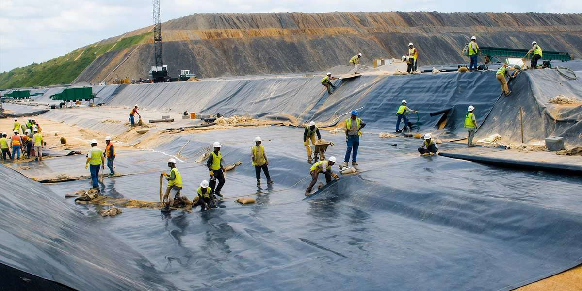
This stage separates a sound installation from a leaking one, and it depends more on crew skill than on anything written in a method statement. Seams in a bituminous geo membrane are fused with a propane torch, softening the bitumen on both overlapping faces until the two flow together under pressure from a roller worked along the joint immediately behind the flame.
Too little heat leaves a cold bond that looks welded, feels welded and is not. Too much burns the bitumen and damages the reinforcement carrying the sheet. The working window between those two failures is learned on site rather than read from a page, which is exactly why crew certification on the specific product being laid is worth writing into the contract.
Weather governs this stage absolutely and without negotiation. No welding onto a damp surface, none during rain, and heightened care when ambient temperature is low enough that the seam loses heat faster than the crew is expecting. A shift lost to weather is inexpensive. A reach of cold bonded seam discovered after impoundment is not, and it is rarely repairable in place.
Every seam is inspected along its full length, supported by peel testing on trial welds at the start of each shift and again whenever conditions, materials or crew change. Defects are cut out, patched with the same material and the same welding method, then retested. Records are kept per seam and per shift, because a lining membrane accepted without a testing record is accepted on trust alone.
One point that catches specifiers out is worth stating plainly. ASTM D6455, the guide covering test method selection for prefabricated bituminous geomembranes, expressly places field seam evaluation outside its scope, while ASTM D7700 covers seam test method selection and does include this material. Specifications that reference only the material standard therefore leave field testing undefined, which is where disputes begin.
Leaks concentrate wherever the sheet meets something that is not sheet. Concrete interfaces need surfaces prepared and primed so the bitumen bonds properly, and strong adhesion to concrete and earthen substrates is one of the reasons this product performs well at these junctions when the detail is followed. Pipe penetrations, inlets, outlets and structure edges each need a detail drawn in advance.
Improvised detailing at a penetration is the single most common source of a slow, untraceable leak, and it is also the one most likely to be blamed on the membrane years later. The sheet in these cases is usually performing exactly as designed, while the failure sits in a junction that was resolved on site by whoever happened to be standing there that afternoon.
The anchor trench is backfilled in layers and compacted properly rather than tipped and levelled. An exposed lining membrane is ballasted against wind uplift from the moment it is laid rather than at the end of the shift, since a sheet that lifts overnight can tear at its anchor line and will certainly need re inspection along every seam it disturbed.
Plant and site traffic stay off the membrane entirely unless a protective layer is specified and already in place beneath them. Where a cover layer forms part of the design, it goes down to programme rather than after the surface has spent several weeks exposed to sun, wind and whatever else the site chooses to store on it in the meantime.
PART TWO
The seven below recur across sites, across states and across contractors, and they are set out here with the stage that produced each one. None requires exotic diagnosis and none is expensive to prevent, which is precisely what makes them worth circulating to a site team before mobilisation rather than reading about them during a leak investigation.
This is the most expensive mistake in lining work and the least visible while it is being made. Angular material left in the bed, or a soft damp spot covered rather than dried and recompacted, produces a puncture or settlement failure discovered only after impoundment. By then the repair means dewatering an entire section and standing down the command it serves.
An under heated seam holds through construction, passes a casual visual check at handover, then separates months later under thermal cycling and hydrostatic load. Trial welds and peel tests at shift start exist specifically to catch this failure before it is buried, which is unfortunate, because they are the first quality control step dropped whenever the programme slips.
Moisture present on either face at the moment of welding prevents proper fusion, full stop. Crews under pressure to finish a reach will weld through light drizzle or onto morning dew and log the seam as complete in good faith. The joint is compromised at the instant it is made, and no subsequent visual inspection will reveal it.
Specified overlap widths quietly get treated as approximate once the roll is moving and the shift is running long. Width drifts downward through the day, and the seam that eventually fails is reliably in the stretch laid last. Marking overlaps physically before welding begins takes a few minutes per panel and removes the variable altogether.
Inlets, outlets and structure junctions are detailed carefully on the drawing and then resolved on site by whoever is present when the crew reaches them. Leaks at these points are slow, difficult to trace and frequently misdiagnosed later as membrane failure, which sends a department into a warranty argument about a sheet that is performing correctly.
A single pass of a loaded vehicle across an unprotected liner causes damage that may be entirely invisible from above, particularly where the subgrade below is firm enough to hide the imprint. This is a supervision failure rather than a technical one, and it happens most often during the rush to complete backfill before a weather window closes.
Without documentation kept per shift and per seam, a department has no way to establish what was tested, by whom, under what conditions or against which acceptance criteria. Years later, when a leak appears and liability is being argued between supplier, installer and contractor, the absence of records tends to settle that argument on its own.
PART THREE
Read the seven together and a pattern becomes difficult to miss. Not one of them is a material problem. Every one is a supervision or crew competence problem, which means the durability of a geo membrane installation is decided by how the work is contracted and monitored rather than by which product appears in the bill of quantities.
That is the practical argument for keeping manufacture and installation under one accountable party. When the organisation that produced the sheet also welds it, the crew has been trained on that specific product, the welding window is known from production data rather than estimated on site, testing protocol arrives with the material, and no gap opens between the supply contract and the workmanship contract for a defect to fall into.
YOOIL Envirotech, a subsidiary of YOOIL Engineering South Korea, commissioned India’s first canal lining project using bituminous geomembrane technology at Nagpur, Maharashtra, in 2019, and works as a single source across design, manufacturing, supply, installation, and subsequent operation and maintenance. That structure exists precisely because the failures listed above sit in the seams between separately contracted parties.
On the Pench project, where repeated canal breaches had made seepage the governing problem, Shri Rahul Morghade, Executive Engineer at VIDC, has recorded that the material exceeded expectations, crediting its resistance to water permeation and to ultraviolet degradation for the long term integrity of the water carriage system. More than 400 projects across four continents sit behind that experience.
If nothing else from this guide reaches a specification document, two clauses should. Require that installation of the bituminous geomembrane liner be carried out by crews trained and certified by the manufacturer of the sheet, and require seam test records to be submitted per shift, referenced to ASTM D7700 methods, as a condition of measurement and payment.
Those two clauses cost nothing at tender stage and remove five of the seven failures set out above. A bituminous geo membrane is a thirty year asset whose performance is effectively decided within about six weeks of site work, so it is worth watching those six weeks closely and worth asking any supplier to walk you through their welding and testing protocol before the first roll reaches the yard.
Standards and sources referenced